CONTINUOUS UNITS (Grease System Compatible)
- Resistance type distribution equipment for continuous distribution systems
- Various flow-rates available. Flow-rate determined by flow numbers (1 to 5)
Continuous Units can be used for either; the resistant type system utilizing the continuous distribution method or in grease distribution systems. Continuous Units allow a controlled delivery of oil or grease and can be attached to Dester Units (DA / DB distribution blocks) or individual lubrication points.
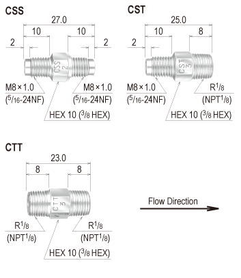
3 types of connector combinations are available (CSS, CST and CTT), each with a selection of 5 oil / grease flow rates. As the classification number increases a step, the flow rate doubles, enabling flow manipulation to the desired effect.
Continuous Units are not to be utilized in conjunction with volumetric type pump (pressure displacement mechanisms).
Form code
Specifications
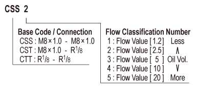
| MODEL CODE |
Connection Size | Flow Class |
Flow Value |
Operating Pressure (MPa) |
Recommended Viscosity(m㎡/s) |
Compatible Connectors | ||
| IN | OUT | IN | OUT | |||||
| CSS Type | M8×1.0 (5/16 – 24NF) |
M8×1.0 (5/16 – 24NF) |
1 | 1.2 | 0.15~2 | 20~500 | PAN4 (PAN4H) |
PAN4 (PAN4H) |
| 2 | 2.5 | |||||||
| CST Type | M8×1.0 (5/16 – 24NF) |
R1/8 (NPT1/8) |
PAN4 (PAN4H) |
※ | ||||
| 3 | 5.0 | |||||||
| CTT Type | R1/8 (NPT1/8) |
R1/8 (NPT1/8) |
4 | 10.0 | ※ | ※ | ||
| 5 | 20.0 | |||||||
※Flow-rate doubles every increment in the unit’s flow classification number.
※Continuous Units are available in inch sizes. Size displayed in ( ), a “H” will be added to the end of the model code.
※The “#” displayed in the “Compatible Connectors / Parts” column indicates that any piping connector that can connect to Rc1/8 and Rp1/8 connections can be used.
※In situations where Continuous Units are to be used for grease lubrication systems, CSS models should be selected.
Drawing